Syntor Xcat
The Syntor Xcat is a plug-in upgrade for the Motorola Syntor X two-way radio. The Xcat replaces the Syntor's memory module with a versatile computer interface. Any VHF low band, VHF high band (range 1 or 2), or UHF Syntor X will work with the Xcat. Earlier Syntors (no X) and the Syntor X 9000 do not work with the Xcat. The Xcat will set up all Syntor X modes without the need for a special programming cable or a PROM programmer. All that is needed is a Windows computer with a serial port and the provided control software. The software is an easy to use Windows GUI. (see photo) Once the Xcat is configured the serial cable may be removed and the Syntor X can be operated with the standard control head in mobile or base station operation. With the serial cable connected computer control of the Syntor X is possible. The radio stays in mode 1 and the Xcat is used like a VFO. Any frequency, tx offset, PL, or DPL can be "dialed" into the radio. The Xcat can band scan and PL/DPL scan under computer control. Another way to use the Xcat is in remote base operation. The Xcat communicates with a repeater controller in either Icom or "Doug Hall" protocol. This web site is about building a remote base with a Syntor X, the Xcat, and a Pacific Research repeater controller. The Xcat was created by Skip Hansen, WB6YMH and Lee Dusbabek, N7LD. Skip and Lee are longtime friends of mine but my only connection with the Xcat is as an end user. I made this site because I think the Xcat is cool. I do not make money from Xcat sales or anything related to the Xcat. The Xcat cost is $73. If you'd like to buy one go to the Xcat web site, groups.yahoo.com/group/xcat/, to contact Skip or Lee. You might find a used one for sale if you ask.
Xcat Features
- Easily setup frequency, P/L, DPL, and scanning.
- Operate as a mobile radio or base station with regular station accessories. Optionally operate under Windows computer control. Or as a remote base with "Doug Hall" or Icom protocol.
- Supports all 32 modes.
- Replaces the Syntor X code plug memory module.
Wiring
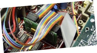
One of the really great things about the Xcat is that it just plugs in and no modifications to the Syntor X are necessary. However, for "Doug Hall" remote base operation, it is necessary to solder three wires from the Xcat to the Syntor X personality board. My Xcat came with a serial ribbon cable and a larger 22 pin multi-color ribbon cable. The three wires that need to be soldered to the Syntor X are as follows:
- Xcat pin 16 (blue) to Syntor X U6 pin 2 on the personality board. I tacked this directly to the IC chip as shown in photo 1.
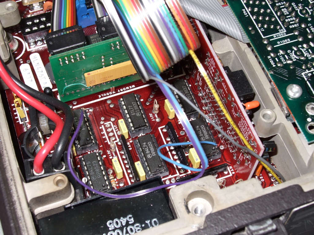
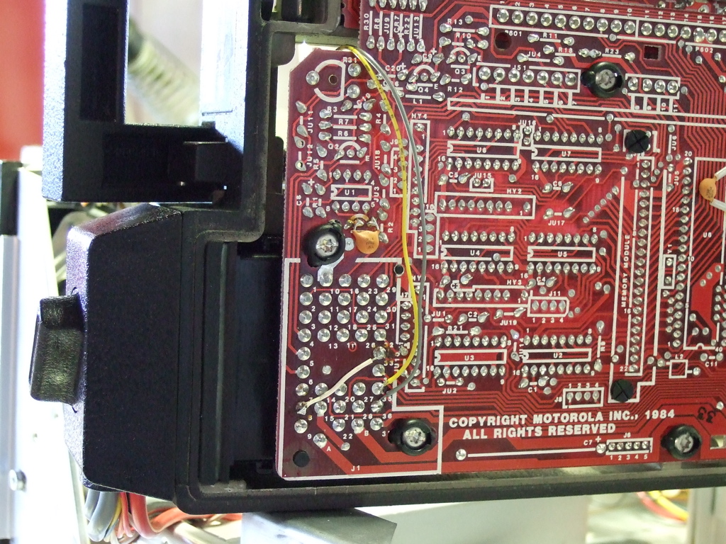
- Xcat pin 4 (yellow) to Syntor X J1-35. This is an unused pin in the Syntor X control cable. This brings out the serial data to connect to the "Doug Hall" data line on the repeater controller. See photo 2.
- Xcat pin 18 (gray) to Syntor X J1-36. This also is an unused pin in the control cable. This brings out serial clock for "Doug Hall" control. See photo 2.
I soldered a fourth wire to test band and PL/DPL scanning. Scanning won't work in "Doug Hall" mode but it's fun to play with on the bench. Xcat pin 17 (violet) goes to U2 pin 15 on the personality board. You must make the COS input selection on the configure tab of the Windows control program. If you forget to do this the audio will be turned off or muted. Be sure to go to the Xcat site and download the xcat_docs.pdf file. As always RTFM!
Control Cable
One could use a control head but it's overkill for a remote base. Besides, mine didn't come with one and they seem hard to come by. If you do use a control head it must be on mode 1. The only control really needed is the squelch. I also wired up a volume control and a speaker for testing. A number of pins need to be grounded or pulled to 12 volts as indicated to make the Syntor X function. Here's a schematic (pdf) of how I wired the cable. You'll need what's sometimes called a charlie-zero-one key to remove the pins from the cable. See repeater-builder.com keys page (look all the way down to the bottom of the Motorola section) and a picture of the key. The narrow part of the key goes towards the body of the pin in order to press on the release. The the pin body (and release) is opposite of the wire crimp. Push the key in hard from the front and pull the wire and pin out the back. I scrounged up an old 800Mhz base station and stripped most of the parts out of it. I used linear taper pots for both the squelch and volume. That's fine for the squelch but I suspect the low volume adjustment would be less abrupt if you use an audio taper.
Audio
The audio gate board may not be needed if your repeater controller gates the audio. I'll post a detailed schematic of the audio gate after I draw it. It's just a 4066 and a 4011. You could do it with a 4053 but I used what I had. I used an on-board 5 volt regulator to keep the levels compatible with the Syntor X and my repeater controller. My Syntor X has a 1.3 volt DC bias and 1.6 volts AC on the DET OUT audio. I didn't have any problems with supply rails or popping to do DC switching. DET OUT is discriminator audio, it needs de-emphasis, so remember to adjust you controller appropriately. On the Pacific Research PE-3 you need to move the jumper from the default of pins 1-2 to pins 2-3 for whichever port you're using. The transmit audio jumper stays on the 1-2 default pins (pre-emphasis).
Interface Cable
The interface cable to the Pacific Research PE-3 board is totally straight forward. I brought out the standard signals (PTT, COR, TX Audio, RX Audio, and GND) plus the "Doug Hall" signals (serial data and clock) to a terminal block that was on the back of the Syntor base. I built a cable with spade connectors on one end and a DB-9 on the other. Only the TX and RX audio leads are shielded.
Syntor Tuning
Tuning up any transceiver requires communications test gear and the Syntor X is no exception. There is a scary label inside the Syntor X that says "Do Not Field Adjust". It's referring to the RF pre-selector which in fact will need adjustment. At least mine did as the sensitivity for 20 db quieting was 10 micro volts at the bottom of two meters. However, if you have access to a spectrum analyzer and a variable RF generator tune up is relatively easy. There is a excellent Syntor tuning guide on KB8ZQZ's Syntor X retuning page and even more information on SYNTOR X Extended Frequency Modifications. No need to repeat all of that here. I'll just hit the highlights.
VCO
On the Blender page there is a lengthy and interesting discussion of how work radios in general and specifically how the synthesized Syntor X works. Even if you know "Radio 101" you should read this page before tuning. Having said that, the whole discussion about VCOs comes down to this one sentence. I quote:
However, if you want to lower the frequency coverage for HAM use only, you can just restore the factory cut which will probably cause some loss at the high end frequency range.
My Syntor X locked fine on receive all the way down to 142 MHz. The transmit would only lock down to about 147.5 MHZ. So I followed the above instructions and soldered in the transmit jumpers. Now I get a solid lock through the entire two meter ham band. I don't know where the low and high transmit lock ends as the Xcat will not transmit out of band without jumping through some hoops which I won't go into now. The receive lock limits are easy to find. Just put the Xcat in band scan and watch the unlock light on the Syntor X. Too cool!
Pre-selector
This is where the spectrum analyzer and frequency generator come in very handy. The generator goes on the antenna and the spectrum analyzer connects to the first mixer input. The Syntor need not be powered on. I just cranked the generator frequency up and down and could easily see where the band pass rolled off. The band pass was from about 148-174 MHz. The KB8ZQZ page said turning the filters in moved the frequency down. So I turned all five in a 1/4 turn and sure enough it moved down. I repeated this process, turning all five filters in the same amount, until the bottom end of the band pass was around 143 Mhz. The top end came down to about 170 Mhz. I ended up giving each of the five filters two full turns clockwise.
Injection Filter
I didn't tune this as I was happy with the results just from tuning the pre-selector. However, there is a bit of room for improvement and spending the extra effort here probably would have brought the Syntor X up to par.
Results
The band pass curve of the pre-selector had a wide sag in the middle and peaked up a bit on the low end before any adjustments were made. This curve remained after adjustment. But that's not such a bad thing for ham operation. May even cut the intermod down a few db. Before touching the Syntor X it's sensivity on 162 Mhz was .3 micro volts for 20 db quieting and about 10 micro volts at 144 MHz. After tuning the pre-selector the sensitivity at 162 Mhz is still .3 but 144 Mhz came down to .6 micro volts. Not red hot but good enough for our noisy hill.